Sometimes the cable on the camera’s pigtail is damaged and the camera doesn’t work anymore. In other cases the RJ45 jack of the camera is damaged, burned, crushed the signal can’t go through.
You scan the network but no IP address shows up. All these problems can be solved by remaking the connection. So, how to rewire a broken Dahua IP camera cable?
This guide shows the color codes of Dahua pinout, the Dahua RJ45 wiring diagram and which pin goes to which color wire in order to make a good connection. For more details with the procedure, we recommend to read this article: How to fix IP security camera’s damaged RJ45 Ethernet connector.
There are various Dahua IP cameras on the market and not all of them follow the same pinout scheme. However, most of them do and below you can see an example the color coded wiring diagram. This is how you work out the pin numbering on RJ45.
Turn the RJ45 plug almost upside down, the copper side face upwards and start the number on the left side. Take a look at the illustration. Each pin is numbered 1 to 8.
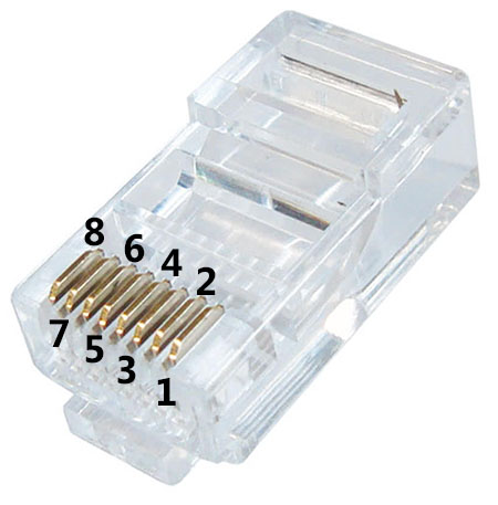 Using this logic you can then map the Dahua color coding. For example, Brown goes to pin 1, Purple goes to pin 2, Orange goes to pin 3, Yellow goes to pin 4 and so forth. This is what you need to know in order to wire a broken Dahua IP camera cable.

Dahua Pinout wiring diagram
Apart from the example shown above, many of the Dahua IP cameras can have a different pinout diagram. Take a look at the picture below, on the left side it’s the RJ45 pinout (T-568B) and the right side the Dahua IP camera PoE pinout (color coded wiring diagram).
 Make the connection as shown on the illustration. For example, grey wire goes to pin 8, brown wire goes to pin 2, blue goes to pin 1 and so on.
 Once you’re done, try if you can see the IP camera on the configuration tool. Then permanently crimp it. This the general guide about the Dahua color coded wiring scheme. The same idea can be applied to other CCTV manufacturers as well.
Note: This wiring guide works for Dahua and their OEM cameras sold under these brands: Activecam, Advidia, Amcrest, Ameta, Ascendent, Backstreet Surveillance, BV Security, CCTV Security Pros, CCTV Star, CP Plus (Orange Line), Dax Networks, eLine, ENS (formerly Eastern CCTV and SavvyTech), Expose, Lorex, GSS, Honeywell, IC Realtime, Ikegami, Impath Networks, Inaxsys, IndigoVision, Infinity CCTV, Innekt, Intelbras, KBVision, Lumixen, Maxron, Montavue, Oco, Optiview, Rhodium, RVI, Saxco, Security Camera King (Elite), Space Technology, Speco, ToughDog, Tyco Holis, Tyco Illustra Essentials, Unisight, VIP Vision, Watchnet, Winic, Zuum.


For HFW2100 and HFW3200
Brown = pin 1
Purple = pin 2
Orange = pin 3
Yellow = pin 4
Blue = pin 6
Grey = pin 7
Error in table for “1000BASE”.
Should be like this:
Pin4 of RJ45 is “DC-”
Pin5 of RJ45 is “DC+”